If you’ve ever tried to use Revit’s “Heating and Cooling Loads” tool, you probably gave up and returned to your trusty Trane Trace or Carrier HAP program. It required a perfect Revit model and produced untrustworthy results.
Revit now has an “Easy Button” for heating and cooling load calculations (and more). It’s in the “Energy Optimization” panel of the Analyze tab. It walks you through the energy analysis process from calculating heating and cooling loads through
The tools in this section include:
- Location
- Energy Settings
- Systems Analysis
- Create/Delete Energy Model
- System Zone
- Generate (Analytical Model)
- Optimize
Location
Analyze tab Energy Optimization panel
 (Location)
Where on earth is your project? Revit’s location tool can be used to locate the closest weather station to your project. Select the tool and the “Location and Site” window opens.
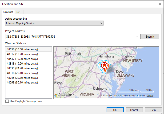
Zoom in/out to find your location and drag the “Location” pin to it. Then select one of the weather stations nearby that are in the list. Alternately, you can access the Default City List, and choose a city close to your site.
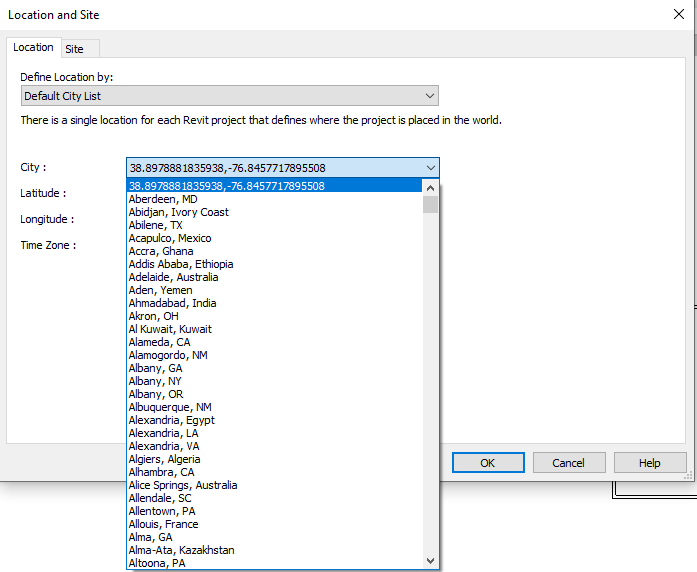
Revit will choose the closest weather station to the city selected. All of the historical weather data for this location is available for hourly energy analysis.
Energy Settings
Analyze tab > Energy Optimization panel > ![]() (Energy Settings)
(Energy Settings)
This activates the Energy Settings window, which provides default settings for a variety of energy parameters.
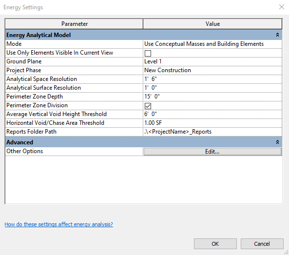
The Mode parameter tells Revit whether you are using massing elements, building elements, or a combination of both. Leave it set to use the combination of both.
Check the box to use only elements visible in the current view. This helps simplify the analytical model.
Project Phase should be set to the current phase you want to consider. Most of the time, this is “New Construction”, but could be a different phase depending on your project.
The analytical resolution parameters will affect the generation time and accuracy of your energy model. If you’re not sure, leave them at the default settings. After you become comfortable using Energy Optimization, you may want to play around with these settings.
Perimeter zones are used to help divide your model into exterior and interior zones. Exterior zones are divided into the four compass exposures, north, south, east, and west. The interior zone does not touch the outside walls of the building. The default zoning is 15 feet from the perimeter of the building to the interior zone boundary.
Leave the zone depth at 15 feet until you feel the need to change it, and make sure the Perimeter Zone Division box is checked.
The two threshold parameters help determine spaces that are unconditioned, like ceiling plenums and utility shafts. If the vertical height of a space is less than 6 feet, or the floor area is less than 1 square foot, these spaces are assumed to be unconditioned. The 6 feet parameter seems to work for me, but the 1 square foot parameter ends up conditioning some large duct shafts. These can be overridden on a case by case basis, but you’ll want to increase this parameter if it becomes annoying.
The Advanced Other option takes you to the meat of the energy settings. This is where you make decisions that impact the building energy use.
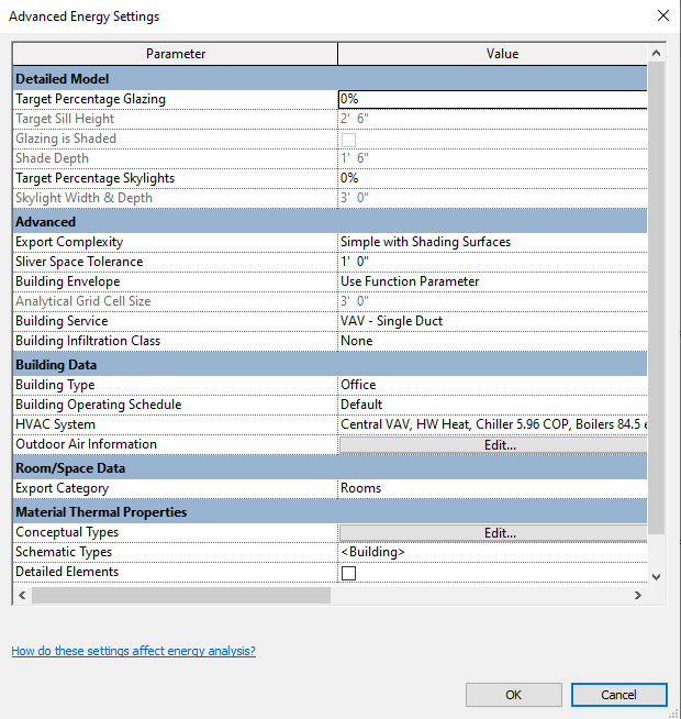
This is where you want to have a copy of your local energy codes handy. The first parameter, Target Percent Glazing, is restricted by most energy codes to around 20-30% of the total wall area unless certain provisions are met. Unless your project is a warehouse, you’ll want windows, so enter a value in this range. If you leave this value at 0%, your building will have no windows!
Export Complexity should be left at “Simple with Shading Surfaces”. This will keep the computation time relatively short, and allow Revit to calculate the effect of shading elements in your model such as adjacent structures, decks, and exterior shades.
If you want to include shading elements, select “Identify Exterior Elements” for the Building Envelope parameter.
To take advantage of exposure zones, choose “VAV – Single Duct” for the building service. This is the most energy efficient option other than ground source heat pumps, which is not listed as an option.
Choose “None” or “Tight” for the building infiltration class.
Building type should match your general building use. If you have a multi-use building, you can select the use on a room by room basis at the room properties level. This option simply sets the default value for your rooms.
The operating schedule tells Revit when the building is occupied. This is used to calculate annual energy consumption.
The HVAC option will vary with the Building Service that you chose. Don’t change this unless you are pretty comfortable with the types of HVAC systems.
The outdoor air information is either per person or per person/area. I use 5 cfm per person plus 0.06 cfm/sf for most buildings. This value can be adjusted at the room level.
The Export Category tells Revit whether you want to export Rooms or Spaces. Engineers used to create spaces in all the rooms and use these spaces to calculate the heating and cooling loads. This is a carryover from that era. I use Rooms now.
Material Thermal Properties tell Revit how fast heat will transfer in/out of the building and how much heat it will store. Conceptual Types are the default properties. Schematic Types will override them when the override box is checked. Detailed Elements override all other types when the checkbox is selected.
Currently (Revit 2024) there is no way to create new properties for the conceptual and schematic types. Ideally, we would be able to create building elements that meet local code requirements for walls, doors, windows, roofs, etc. When performing initial HVAC systems sizing, it’s nice to be able to start with a “meets code” building.
Systems Analysis
Analyze tab > Energy Optimization panel > Systems Analysis ![]()
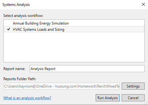
This tool simply tells Revit whether to run a HVAC Systems Loads and Sizing or an Annual Building Energy Simulation Report. Loads and sizing must be done prior to the annual energy simulation.
Create/Delete the Energy Model
Before you create an energy model, you must have a building consisting of massing elements with floors, architectural room bounding elements like walls, floors, and roofs, or a combination of these. If these are in place, Revit will create an energy model based on the location, energy settings, and type of analysis you have selected.
If you’ve checked the “Use Only Elements Visible in Current View” box in the Energy Settings window (and you should), open a 3D view that shows only the massing elements and architecture that you want to include in the energy model. This should include any nearby structures (represented by mass elements with no mass floors) that will shade the building.
Click Analyze tab Energy Optimization panel
 (Create Energy Model) and several things will happen.
- The following views will be created:
- 3D Analytical Spaces
- 3D System-Zones
- The following schedules will be created:
- Analytical Spaces
- Analytical Surfaces
Outdoor air flow will be calculated based on the selection you made under Advanced Energy Settings, using the area of the space and occupancy rates selected under Building Type. Other parameters will populate based on your energy settings entries.
Once the model is set up, it’s ready to analyze. You may want to add some HVAC zones before running the analysis, but this is not necessary.
When you make changes to your model (as it develops), you need to delete the existing energy model and create a new one that contains your current model. When you created the energy model, the icon changed from  to
to ![]() and your option is now to delete the energy model. Simply delete the old one and create a new one.
and your option is now to delete the energy model. Simply delete the old one and create a new one.
Creating Zones
Analyze tab > Energy Optimization panel > System – Zone (SZ) ![]()
As you progress your design from conceptual mass objects to architectural elements such as rooms, you’ll want to group rooms together by similar heating/cooling needs. You want to find a balance between the level of comfort and system cost. The most expensive system allows each space to control its temperature. The most miserable system allows one room to control the entire building. That room is usually the CEO’s office.
When you select the system zone icon, you are placed in the draw lines/shapes mode. Simply draw line(s) in the rooms that you want to include in the zone and select the big green checkmark to complete the zone. ![]() Each use of this tool creates only one zone.
Each use of this tool creates only one zone.
Be careful when creating zones. The zone tool does not always default to the level of the view in which you’re working. It may stay on the last level on which it was used.
Generate the Analytical Model
Analyze tab > Energy Optimization panel > ![]()
When you select this tool, you get the following warning:
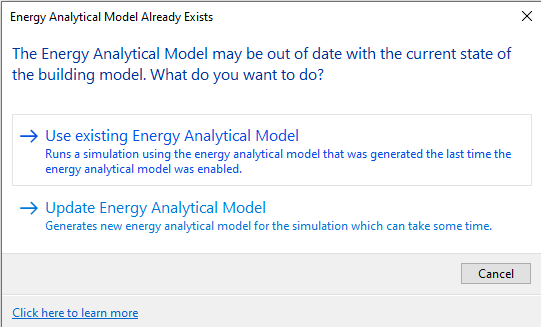
I always choose to update until the length of time it takes becomes unbearable. This tool sends your model to Autodesk Insight to run the calculations, so you can work on other stuff while you wait.
You will shortly receive an email from Insight informing you that your model has been received and is being processed.
Later, you will receive an email (I actually received three of them) notifying you that your analysis is complete, along with a link to Insight.
Click the link and you will be taken to the Insight web page for your model and see how it performs along with a lot of tools to help you improve the energy use. Insight is a topic for another blog post, and it may be the selling point that brings engineers to Autodesk for building energy analysis.
The video below lays out the direction Autodesk is moving to aid designers in reducing the total carbon footprint of buildings.
Optimize
When the energy analysis is complete, you will receive an email containing a link to the model in Insight. You can click on the link and go directly to the model in Insight.
From Revit, click Analyze tab Energy Optimization panel
 (Optimize).
Either of these steps will take you to your energy model in the Insight website.
I won’t go into detail on the use of Insight for energy modeling. Just note that it displays your building energy use in Cost per square foot per year and offers categories that can be modified to improve that number.
The categories are:
- Building orientation
- Window shades
- Window glass properties
- Window/Wall ratio
- Wall construction
- Roof construction
- Infiltration
- Lighting efficiency
- Daylighting and occupancy controls
- Plug load efficiency
- HVAC systems
- Operating schedule
- Solar panel efficiency
- Solar panel surface coverage
- Solar panel payback limit
As you can see, there are a lot of considerations when designing a building for optimum energy use.
