To access the tool, select the element you want to change, right click and choose “Override Graphics in View”:
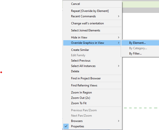
You can then choose from the following options to change the appearance of your selected element:
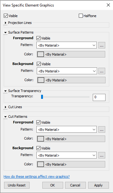
Projection Lines
- Represent edges of objects not intersecting the view’s cut plane
- Show outlines of elements seen from a distance or below the cut plane
- Typically thinner and lighter than cut lines
Surface Patterns
- Repeating designs applied to element surfaces
- Represent materials or provide visual distinction
- Example: Brickwork pattern on a wall
Surface Transparency
- Visual property making elements appear see-through
- Adjustable from 0% (opaque) to 100% (invisible)
- Enhances depth and layering in views
Cut Lines
- Represent elements intersecting the view’s cut plane
- Usually thicker and more prominent than projection lines
- Show internal structure of intersected elements
Cut Patterns
- Graphical representations where elements intersect the cut plane
- Illustrate internal composition or structure of materials
- Appear in plan, section, or elevation views
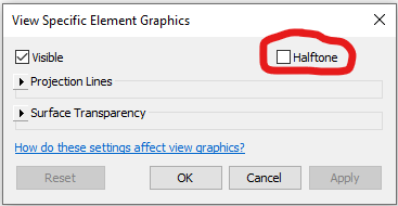
Half Tone
A small check box in the View Specific Element Graphics window allows you to fade the element to “half tone”.
Effectively combining foreground and background patterns allow Revit users to create more detailed and visually appealing material representations in their architectural models and drawings.